 |
||||||||||||||||||||||||||||||||||||||||||||||||||||||||||||||||||||||||||||||||||||||||||||||||||||||||||||||||||||||||||||||||||||||||||||||||||||||||||||||||||
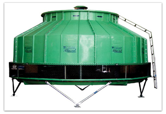
| FRP Cooling Towers are manufactured with Glass reinforced plastic mostly in wind with standing bottle type and square type models. It is a mechanical type Counter Flow Tower. FRP Cooling tower intakes the air from bottom and discharge the waste heat at the top. Since the water is traveling from top and the air passes from bottom to top, the water droplet have more direct contact time with air. The wet cooling Towers are cooled with the help of evaporating some proportionate quantity of cirulating water.
The bottle type tower casing is filled with Honeycomb type PVC FILLS. The rotating water distributor sprinkler is fixed in the top of the inlet pipeline and the same distributes the hot water evenly over the Honeycomb Fill media. The sprinkler will be operated with self-propulsion system. The PVC Fills is corrugated with channels between each flutes to prevent the blockage and giving more and large surface area per unit volume. The cold air meets the cold water at the bottom of the infill providing maximum evaporation and heat transfer in the infill. Finally FRP Cooling Towers are more compact, light in weight, least power consumption, long-lasting, Durable and lowest maintenance expenditure. Since Epoxy Coated / Hot dip galvanized structural and zinc plated fasteners (stainless steel fasteners on extra cost) are used, FRP Towers are corrosion Free. Adjustable pitch, Aluminium [LM-6] or FRP Fan Blades are directly mounted on the Electric motor [IP 55, with Stainless steel shaft, TEFC Special type cooling tower motor] to avoid excess power consumption and unnecessary gear driven problems. All moving parts can be easily approached from top. So easy maintenance is possible. Smaller capacities are factory assembled and just bolting at site is enough. However higher capacities are assembled into the site only to avoid excess transportation cost. Our range includes 10 TR to 500 TR in single cell and multiple cells are used for further capacities. |
||||||||||||||||||||||||||||||||||||||||||||||||||||||||||||||||||||||||||||||||||||||||||||||||||||||||||||||||||||||||||||||||||||||||||||||||||||||||||||||||||
» Normal TR capacity has been computed on the basis of water circulation rate of 4 USGPM/TR at 95.5-90-83 0F conditions.(1 USGPM=4.543 LPM) |
||||||||||||||||||||||||||||||||||||||||||||||||||||||||||||||||||||||||||||||||||||||||||||||||||||||||||||||||||||||||||||||||||||||||||||||||||||||||||||||||||

